Transparent shape with different corner radius
Posted: April 11th, 2019, 1:24 pm
I wonder how to make a transparent shape with different corner radius like this one:
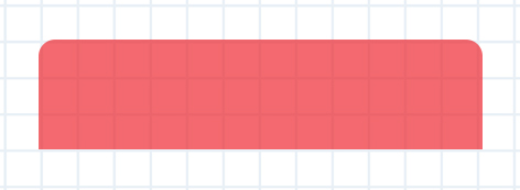
For example:Pul53dr1v3r wrote: ↑April 11th, 2019, 1:24 pm I wonder how to make a transparent shape with different corner radius like this one:
Code: Select all
[MeterRectangle]
Meter=Shape
X=2
Y=2
Shape=Rectangle 0,0,200,60,10 | Extend MyModifiers1
Shape2=Rectangle 0,40,200,60 | Extend MyModifiers1
Shape3=Combine Shape | Union Shape2
MyModifiers1=Fill Color 255,0,0,120 | StrokeWidth 0 | Stroke Color 0,0,0,0Code: Select all
[MeterShape]
Meter=Shape
Shape=Rectangle 0,0,400,150,15 | StrokeWidth 0 | Fill Color 255,0,0,255
Shape2=Rectangle 0,40,400,110
Shape3=Combine Shape | Union Shape2
It should be noted that there is never any need to put attribute modifiers like StrokeWidth or Fill Color on "child" shapes you intend to Combine. The combined shape will always use the attribute modifiers of the primary (first) "parent" shape.balala wrote: ↑April 11th, 2019, 1:40 pm For example:Code: Select all
[MeterRectangle]
Meter=Shape
X=2
Y=2
Shape=Rectangle 0,0,200,60,10 | Extend MyModifiers1
Shape2=Rectangle 0,40,200,60 | Extend MyModifiers1
Shape3=Combine Shape | Union Shape2
MyModifiers1=Fill Color 255,0,0,120 | StrokeWidth 0 | Stroke Color 0,0,0,0
Thx guys. I did a small modification to get a classic illusto bg.jsmorley, balala wrote:
Code: Select all
[MeterBackground]
Meter=Shape
X=2
Y=2
Shape=Rectangle 3,5,198,120,5 | Fill Color 0,0,0,150 | StrokeWidth 0.5 | Stroke Color 160,160,160,200
Shape2=Rectangle 3,5,198,25,5 | StrokeWidth 0 | Fill Color 0,0,0,60
Shape3=Rectangle 3,20,198,10
Shape4=Combine Shape2 | Union Shape3Yes, right, I just wrote that code quickly and...jsmorley wrote: ↑April 11th, 2019, 1:45 pm It should be noted that there is never any need to put attribute modifiers like StrokeWidth or Fill Color on "child" shapes you intend to Combine. The combined shape will always use the attribute modifiers of the primary (first) "parent" shape.
I would also note that there is no need for a Stroke Color if StrokeWidth is equal to zero.
Lastly, I would suggest that since you are going to move the child shape "down", so the top corners of the child shape don't interfere with the top corners of the parent shape, you need to then also make the child correspondingly "shorter" if you want the overall size to remain the same.
Code: Select all
[Rainmeter]
Update=1000
SkinHeight=120
SkinWidth=210
AccurateText=1

[MeterBackground]
Meter=Shape
Shape=Rectangle 6,7,196,104,5 | Fill Color #ShapeBodyColor#,#ShapeBodyOpacity# | StrokeWidth 1.0 | Stroke Color 160,160,160,200
Shape2=Rectangle 6,7,196,25,5
Shape3=Rectangle 6,22,196,10
Shape4=Combine Shape2 | Union Shape3
Shape5=Combine Shape | Exclude Shape4
Shape6=Rectangle 6,7,196,25,5 | Fill Color #ShapeTopColor#,#ShapeTopOpacity# | StrokeWidth 1.0 | Stroke Color 160,160,160,200
Shape7=Rectangle 6,22,196,10
Shape8=Combine Shape6 | Union Shape7

[Variables]
ShapeTopColor=0,0,0
ShapeTopOpacity=200
ShapeBodyColor=0,0,255
ShapeBodyOpacity=150
Code: Select all
[Rainmeter]
Update=1000
AccurateText=1
SkinHeight=120
SkinWidth=210

[Variables]
ShapeTopColor=0,0,0
ShapeTopOpacity=200
ShapeBodyColor=0,0,255
ShapeBodyOpacity=150

[MeterBackground]
Meter=Shape
; The "frame"
Shape=Rectangle 6,7,196,104,5 | StrokeWidth 1 | Stroke Color 160,160,160,255 | Fill Color 0,0,0,0
; The "top" shape
Shape2=Rectangle 6.5,7.5,195.5,25,5 | StrokeWidth 0 | Fill Color #ShapeTopColor#,#ShapeTopOpacity#
Shape3=Rectangle 6.5,15,195.5,20
Shape4=Combine Shape2 | Union Shape3
; The "bottom" shape
Shape5=Rectangle 6.5,35,195.5,75.5,5 | StrokeWidth 0 | Fill Color #ShapeBodyColor#,#ShapeBodyOpacity#
Shape6=Rectangle 6.5,35,195.5,20
Shape7=Combine Shape5 | Union Shape6
Thx for the answer and the explanation.
Code: Select all
[Rainmeter]
Update=1000
SkinHeight=(154*#Scale#+39*#Scale#*Clamp(#SkinState#,0,1))
SkinWidth=(#BgWidth#*#Scale#)
OnRefreshAction=[!CommandMeasure "MeasureRun" "Run"][!EnableMeasure "MeasureSkinState"]
AccurateText=1
; ::::::::::SkinHeight determinator::::::::::
; 1Core-118,   2Cores-130,  4Cores-154,  6Cores-178,  8Cores-202,  10Cores-226, 12Cores-250,
; 14Cores-274, 16Cores-298, 18Cores-322, 20Cores-346, 22Cores-370, 24Cores-394
; 26Cores-418, 28Cores-442, 30Cores-466, 32Cores-490, 34Cores-514, 36Cores-538)

[MeterBackground]
Meter=Shape
Shape=Rectangle 6,7,197,(104+39*#SkinState#+12*([MeasureRun]-1)),5 | Fill Color 0,0,0,0 | StrokeWidth 0.5 | Stroke Color 160,160,160,200
Shape2=Rectangle 6.5,7.5,196,25,5 | StrokeWidth 0 | Fill Color #ShapeTopColor#,#ShapeTopOpacity#
Shape3=Rectangle 6.5,15,196,20
Shape4=Combine Shape2 | Union Shape3
Shape5=Rectangle 6.5,35,196,(75.5+39*#SkinState#+12*([MeasureRun]-1)),5 | StrokeWidth 0 | Fill Color #ShapeBodyColor#,#ShapeBodyOpacity#
Shape6=Rectangle 6.5,35,196,20
Shape7=Combine Shape5 | Union Shape6

[Variables]
.
.
.
SkinState=1
.
BgHeight=150
BgWidth=210
Scale=1.50
.
.
.
[MeasureRun]
Measure=Plugin
Plugin=RunCommand
Parameter=WMIC CPU Get NumberOfLogicalProcessors
State=Hide
OutputType=ANSI
RegExpSubstitute=1
Substitute="\n":"","NumberOfLogicalProcessors":""
FinishAction=[!EnableMeasure "MeasureRunCond"][!EnableMeasure "MeasureSkinState"][!UpdateMeasure "MeasureSkinState"]
.
.
.
Code: Select all
[Rainmeter]
...
SkinHeight=#SKIN.H#
...

[Variables]
SKIN.H=((118 + (%NUMBER_OF_PROCESSORS% - 1) * 12)*#Scale#+39*#Scale#*Clamp(#SkinState#,0,1))
...