It is currently April 19th, 2024, 7:53 pm
Transparent shape with different corner radius
-
pul53dr1v3r

- Posts: 442
- Joined: July 30th, 2014, 10:30 am
Transparent shape with different corner radius
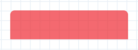
I wonder how to make a transparent shape with different corner radius like this one:
-
balala

- Rainmeter Sage
- Posts: 16146
- Joined: October 11th, 2010, 6:27 pm
- Location: Gheorgheni, Romania
Re: Transparent shape with different corner radius
For example:Pul53dr1v3r wrote: ↑April 11th, 2019, 1:24 pm I wonder how to make a transparent shape with different corner radius like this one:
Code: Select all
[MeterRectangle]
Meter=Shape
X=2
Y=2
Shape=Rectangle 0,0,200,60,10 | Extend MyModifiers1
Shape2=Rectangle 0,40,200,60 | Extend MyModifiers1
Shape3=Combine Shape | Union Shape2
MyModifiers1=Fill Color 255,0,0,120 | StrokeWidth 0 | Stroke Color 0,0,0,0-
jsmorley

- Developer
- Posts: 22629
- Joined: April 19th, 2009, 11:02 pm
- Location: Fort Hunt, Virginia, USA
Re: Transparent shape with different corner radius
Code: Select all
[MeterShape]
Meter=Shape
Shape=Rectangle 0,0,400,150,15 | StrokeWidth 0 | Fill Color 255,0,0,255
Shape2=Rectangle 0,40,400,110
Shape3=Combine Shape | Union Shape2
You do not have the required permissions to view the files attached to this post.
-
jsmorley
- Developer
- Posts: 22629
- Joined: April 19th, 2009, 11:02 pm
- Location: Fort Hunt, Virginia, USA
Re: Transparent shape with different corner radius
It should be noted that there is never any need to put attribute modifiers like StrokeWidth or Fill Color on "child" shapes you intend to Combine. The combined shape will always use the attribute modifiers of the primary (first) "parent" shape.balala wrote: ↑April 11th, 2019, 1:40 pm For example:Code: Select all
[MeterRectangle]
Meter=Shape
X=2
Y=2
Shape=Rectangle 0,0,200,60,10 | Extend MyModifiers1
Shape2=Rectangle 0,40,200,60 | Extend MyModifiers1
Shape3=Combine Shape | Union Shape2
MyModifiers1=Fill Color 255,0,0,120 | StrokeWidth 0 | Stroke Color 0,0,0,0
I would also note that there is no need for a Stroke Color if StrokeWidth is equal to zero.
Lastly, I would suggest that since you are going to move the child shape "down", so the top corners of the child shape don't interfere with the top corners of the parent shape, you need to then also make the child correspondingly "shorter" if you want the overall size to remain the same.
-
pul53dr1v3r
- Posts: 442
- Joined: July 30th, 2014, 10:30 am
Re: Transparent shape with different corner radius
Thx guys. I did a small modification to get a classic illusto bg.jsmorley, balala wrote:
Code: Select all
[MeterBackground]
Meter=Shape
X=2
Y=2
Shape=Rectangle 3,5,198,120,5 | Fill Color 0,0,0,150 | StrokeWidth 0.5 | Stroke Color 160,160,160,200
Shape2=Rectangle 3,5,198,25,5 | StrokeWidth 0 | Fill Color 0,0,0,60
Shape3=Rectangle 3,20,198,10
Shape4=Combine Shape2 | Union Shape3-
balala
- Rainmeter Sage
- Posts: 16146
- Joined: October 11th, 2010, 6:27 pm
- Location: Gheorgheni, Romania
Re: Transparent shape with different corner radius
Yes, right, I just wrote that code quickly and...jsmorley wrote: ↑April 11th, 2019, 1:45 pm It should be noted that there is never any need to put attribute modifiers like StrokeWidth or Fill Color on "child" shapes you intend to Combine. The combined shape will always use the attribute modifiers of the primary (first) "parent" shape.
I would also note that there is no need for a Stroke Color if StrokeWidth is equal to zero.
Lastly, I would suggest that since you are going to move the child shape "down", so the top corners of the child shape don't interfere with the top corners of the parent shape, you need to then also make the child correspondingly "shorter" if you want the overall size to remain the same.
-
pul53dr1v3r
- Posts: 442
- Joined: July 30th, 2014, 10:30 am
Re: Transparent shape with different corner radius
How to get rid of the inner stroke between the two combined shapes in this case:

Code: Select all
[Rainmeter]
Update=1000
SkinHeight=120
SkinWidth=210
AccurateText=1

[MeterBackground]
Meter=Shape
Shape=Rectangle 6,7,196,104,5 | Fill Color #ShapeBodyColor#,#ShapeBodyOpacity# | StrokeWidth 1.0 | Stroke Color 160,160,160,200
Shape2=Rectangle 6,7,196,25,5
Shape3=Rectangle 6,22,196,10
Shape4=Combine Shape2 | Union Shape3
Shape5=Combine Shape | Exclude Shape4
Shape6=Rectangle 6,7,196,25,5 | Fill Color #ShapeTopColor#,#ShapeTopOpacity# | StrokeWidth 1.0 | Stroke Color 160,160,160,200
Shape7=Rectangle 6,22,196,10
Shape8=Combine Shape6 | Union Shape7

[Variables]
ShapeTopColor=0,0,0
ShapeTopOpacity=200
ShapeBodyColor=0,0,255
ShapeBodyOpacity=150-
jsmorley
- Developer
- Posts: 22629
- Joined: April 19th, 2009, 11:02 pm
- Location: Fort Hunt, Virginia, USA
Re: Transparent shape with different corner radius
I would do something like this:
So in short, I'm first drawing an empty "frame" around the area for my overall shape, so I get the "stroke" I want.
Then I draw each of the individual "top" and "bottom" shapes, with no "stroke", and then use Combine to eliminate the corner radius from the bottom of the "top" shape, and the top of the "bottom" shape. Size and position these shapes so they fit within, but don't overlap, the "frame" we first drew. Remember that strokes are 1/2 "inside" and 1/2 "outside" the shape they define. That is why there are some fractional heights and widths.
If you have a rectangle defined at 2,2 and a StrokeWidth of 1, the stroke is actually drawn on 1.5,1,5 and extends to 2.5,2.5
Not quite sure why you have the shape "inset" in the skin and have SkinWidth and SkinHeight defined, but perhaps it is to simplify "Snap to edges", and that is up to you. I more or less went with what you had.
In truth, probably the right way to do this is to just draw the "top" and "bottom" shapes using a Path shape, and just exclude the stroke on the bits of the path where you don't want them, using SetNoStroke. This could be done with 2 shapes instead of 7. Having said that, Bézier curves (for the corners) are a bit outside my wheelhouse, so I went with the brute force approach.
Code: Select all
[Rainmeter]
Update=1000
AccurateText=1
SkinHeight=120
SkinWidth=210

[Variables]
ShapeTopColor=0,0,0
ShapeTopOpacity=200
ShapeBodyColor=0,0,255
ShapeBodyOpacity=150

[MeterBackground]
Meter=Shape
; The "frame"
Shape=Rectangle 6,7,196,104,5 | StrokeWidth 1 | Stroke Color 160,160,160,255 | Fill Color 0,0,0,0
; The "top" shape
Shape2=Rectangle 6.5,7.5,195.5,25,5 | StrokeWidth 0 | Fill Color #ShapeTopColor#,#ShapeTopOpacity#
Shape3=Rectangle 6.5,15,195.5,20
Shape4=Combine Shape2 | Union Shape3
; The "bottom" shape
Shape5=Rectangle 6.5,35,195.5,75.5,5 | StrokeWidth 0 | Fill Color #ShapeBodyColor#,#ShapeBodyOpacity#
Shape6=Rectangle 6.5,35,195.5,20
Shape7=Combine Shape5 | Union Shape6
So in short, I'm first drawing an empty "frame" around the area for my overall shape, so I get the "stroke" I want.
Then I draw each of the individual "top" and "bottom" shapes, with no "stroke", and then use Combine to eliminate the corner radius from the bottom of the "top" shape, and the top of the "bottom" shape. Size and position these shapes so they fit within, but don't overlap, the "frame" we first drew. Remember that strokes are 1/2 "inside" and 1/2 "outside" the shape they define. That is why there are some fractional heights and widths.
If you have a rectangle defined at 2,2 and a StrokeWidth of 1, the stroke is actually drawn on 1.5,1,5 and extends to 2.5,2.5
Not quite sure why you have the shape "inset" in the skin and have SkinWidth and SkinHeight defined, but perhaps it is to simplify "Snap to edges", and that is up to you. I more or less went with what you had.
In truth, probably the right way to do this is to just draw the "top" and "bottom" shapes using a Path shape, and just exclude the stroke on the bits of the path where you don't want them, using SetNoStroke. This could be done with 2 shapes instead of 7. Having said that, Bézier curves (for the corners) are a bit outside my wheelhouse, so I went with the brute force approach.
You do not have the required permissions to view the files attached to this post.
-
pul53dr1v3r
- Posts: 442
- Joined: July 30th, 2014, 10:30 am
Re: Transparent shape with different corner radius
Thx for the answer and the explanation.
As far as the SkinHeight and SkinWidth are concerned, i don't need them here(but smh they are here), but don't now how to make a skin like this (see the code) not using that option, if possible. I'm stuck with SkinHeight since it hasn't got the dynamic value ability and have to enter the values manually for every CPU Cores number.
I'd like if it can be done not using the options.
Here i have 4 cores (must enter manually 154 into SkinHeight)
Code: Select all
[Rainmeter]
Update=1000
SkinHeight=(154*#Scale#+39*#Scale#*Clamp(#SkinState#,0,1))
SkinWidth=(#BgWidth#*#Scale#)
OnRefreshAction=[!CommandMeasure "MeasureRun" "Run"][!EnableMeasure "MeasureSkinState"]
AccurateText=1
; ::::::::::SkinHeight determinator::::::::::
; 1Core-118,   2Cores-130,  4Cores-154,  6Cores-178,  8Cores-202,  10Cores-226, 12Cores-250,
; 14Cores-274, 16Cores-298, 18Cores-322, 20Cores-346, 22Cores-370, 24Cores-394
; 26Cores-418, 28Cores-442, 30Cores-466, 32Cores-490, 34Cores-514, 36Cores-538)

[MeterBackground]
Meter=Shape
Shape=Rectangle 6,7,197,(104+39*#SkinState#+12*([MeasureRun]-1)),5 | Fill Color 0,0,0,0 | StrokeWidth 0.5 | Stroke Color 160,160,160,200
Shape2=Rectangle 6.5,7.5,196,25,5 | StrokeWidth 0 | Fill Color #ShapeTopColor#,#ShapeTopOpacity#
Shape3=Rectangle 6.5,15,196,20
Shape4=Combine Shape2 | Union Shape3
Shape5=Rectangle 6.5,35,196,(75.5+39*#SkinState#+12*([MeasureRun]-1)),5 | StrokeWidth 0 | Fill Color #ShapeBodyColor#,#ShapeBodyOpacity#
Shape6=Rectangle 6.5,35,196,20
Shape7=Combine Shape5 | Union Shape6

[Variables]
.
.
.
SkinState=1
.
BgHeight=150
BgWidth=210
Scale=1.50
.
.
.
[MeasureRun]
Measure=Plugin
Plugin=RunCommand
Parameter=WMIC CPU Get NumberOfLogicalProcessors
State=Hide
OutputType=ANSI
RegExpSubstitute=1
Substitute="\n":"","NumberOfLogicalProcessors":""
FinishAction=[!EnableMeasure "MeasureRunCond"][!EnableMeasure "MeasureSkinState"][!UpdateMeasure "MeasureSkinState"]
.
.
.
I've made "SkinHeight determinator" just to know what are the exact values for certain Core numbers to avoid either skin cut or inability to move the skin t0 the bottom edge.
I will go with this 7 shapes for the time being until i get some more skills with the Paths, curves... Thx for the effort and advices mate! Any your suggestion is welcome since your knowledge of this is many times above mine. More or less the same goes to balala, electic...
-
ikarus1969

- Posts: 571
- Joined: February 28th, 2011, 3:20 pm
- Location: Vienna, Austria
Re: Transparent shape with different corner radius
Just try the following for SkinHeight:
define a variable that holds the code for your desired skin-height, let's call it SKIN.H and use that single variable. That way i got it working.
%NUMBER_OF_PROCESSORS% is an environment variable that holds the same number as the result of your measure MeasureRun but is automatically resolved by Rainmeter (see documentation https://docs.rainmeter.net/manual-beta/variables/?#EnvironmentVariables).
define a variable that holds the code for your desired skin-height, let's call it SKIN.H and use that single variable. That way i got it working.
Code: Select all
[Rainmeter]
...
SkinHeight=#SKIN.H#
...

[Variables]
SKIN.H=((118 + (%NUMBER_OF_PROCESSORS% - 1) * 12)*#Scale#+39*#Scale#*Clamp(#SkinState#,0,1))
...